I originally wrote this guide in 2012 to help gamers and esports players better understand exactly how the mouse works and choose the right tool for their needs. The original can be found on Overclock.net.
Table of Contents
- Introduction
- A Short Overview of Mouse Sensors
- Choosing a Mousepad
- Technical Aspects of Mice Defined & Explained
- Appendix
Introduction
The following article is something that I have been working on for some time regarding mouse technology, and my understanding of the field. I have a lot of information to impart on this topic and being quite technical it can be rather dense in places, so I'll try to keep this intro somewhat brief.
In beginning this process of understanding mouse technology, I found that there was at first a daunting amount of information that I needed to know in order to simply understand how a mouse performs, what is important to look for, how performance is influenced by certain factors, etc... I also found that while some websites tended to have more information than others that there was still no centralized location where all of this information could easily be found, or be found free of bias. The other major issue that I ran into was that many times I would be searching and find information that would simply confuse matters further or contradict previous information that I had obtained, thus further obfuscating the landscape. In an effort to make things clear for myself and to help everyone to understand mouse technology, I decided to start a comprehensive write-up on the topic and cover pretty much everything that I've learned in the last six or so months.
So why is all of this technical stuff important anyway? As gamers, and competitive ones at that, we are constantly tasking our hardware to perform with a certain level of stability and predictability. For most hardware, benchmarking has been easy in part because we know what to look for and that we have a large, dedicated infrastructure that helps to test and disseminate this data. For mice, this level of detailed information and infrastructure has only in the last few years been starting to surface with more and more regularity due to a growing community effort (though it may be some time before major technology sites like AnandTech, or Tom's Hardware begin to include these testing procedures). Take for example reviews at Overclocked.net or on ESReality.com; it's becoming more and more common nowadays to find an evaluation of a mouse that has multiple pictures, a complete technical review, and lots of benchmarking data.
For a long time previous to this, trying to benchmark mice was more a process of "feeling" which mice seemed better, and as there weren't standardized testing procedures or applications, subjectivity ruled. This leaves a rather unpalatable taste in our mouths because benchmarking should describe certain aspects of performance where personal feelings... Well, you get the picture. Of course, with all of this data emerging more frequently it falls to us as the user to know what everything means, and how and what data relates to what performance-wise; this is where this project attempts to help with.
It is important to remember throughout this write-up that when describing or benchmarking certain areas of performance, that the standard held in these conditions is theoretical "perfect" tracking or performance conditions. From a technical standpoint, errors or discrepancies from this benchmarking standard may seem more exaggerated than they will appear to the average user, though, how pronounced these performance considerations, errors, or areas are perceived by each person has largely to do with how sensitive they are to such things.
As a final note, please see the original credits footnote for acknowledgments to the original authors of *much* of this information. Without their expertise, help, and insight into the subject this project would have been much less thorough, and much of the credit belongs to them as a result.
A Short Overview of Mouse Sensors
I would normally delve into a detailed explanation of this topic, but because there is just so much variable information regarding sensors and places that can go wrong performance-wise, this section will remain somewhat brief remaining more of a "how to" in discerning what to look for in sensor performance. You might find however that your first question is, What is the perfect mouse sensor? The answer is simple, it hasn't been made yet.
Sensor Operation
The basic way a sensor operates is largely the same over all mice, though there are some rather large differences in how each sensor goes about acquiring movement data. In traditional methods such as sensors manufactured by Avago Technologies, the image acquisition system (IAS) first captures the movement of the mouse, usually in many thousands of frames per second (see FPS and Pixel Resolutin), which are then processed by the digital signal processor (DSP) of the sensor in order to determine the (delta) Δx/Δy values (through direction and magnitude of movement). From here a microcontroller unit (MCU) translates this data into USB or PS/2 signals, which are then sent to the host controller (PC).
The Philips Twin-Eye laser sensors register movement quite differently than traditional image capture sensors using a "Doppler shift" method. In PTE sensors, a photo diode detects fluctuations in the laser power and is output to a application-specific integrated circuit (ASIC) which conditions and digitizes the signals. The dual laser system is needed in this method in order to detect directional movement, and is done by analyzing changes in laser temperature and consequent modulation of the laser frequency. As a result of the Doppler technology in PTE sensors they do not gather information in frames but are able to detect these laser fluctuations up to a certain speed, rated in m/s.
What to Consider
When looking into the type of sensor a mouse uses, a few things need to be kept in mind. Just because a specific sensor is used in a number of mice doesn't mean that the performance for each of these mice will be the same (build quality, lenses, sensor implementation, and firmware can all influence performance), but it should mean that the general performance traits will be relatively similar. Unfortunately this also means that if there are tracking or hardware related errors that they may also carry over.
Another important consideration in looking at sensor performance is what surfaces work well with which mice and which ones will not (see Choosing a Mousepad), and finally whether a sensor is optical or laser, and how each of these types of sensors perform (laser sensors can detect surface imperfections at 20x the rate of optical sensors, this does not necessarily make them more accurate however).
The three main resources you can use to immediately find a great deal information are the OCN Mouse Reference Thread by Skylit (the main resource for which sensors are in which mice), the "Flawless" Sensor List on ESReality (somewhat 'colored', but a nice, quick overview), and the much older ESReality MouseScore 2007 (while still somewhat useful, there are a few shortcomings to the methodology). If you need more specific information after looking these over, head into the OCN or ESR forums which have an incredible amount of detailed information (highly recommended).
When trying to figure out which sensors are "better", where "better" is usually a subjective opinion, you need to ask yourself a few fundamental questions about what you are looking for in a mouse:
- How much CPI do I use/What is my sensitivity?*
- What is the perfect control speed and malfunction rate of the mouse?
- Can I work with a mouse that has angle snapping (can it be turned on/off or adjusted)?
- Can I work with a mouse that has +/- acceleration problems (small or large amounts)?
- How much of an issue is "jitter/ripple" (and which mice and mousepads work well, or don't with one another)?
- Will the LOD of my mouse affect my tracking accuracy (would a tape fix be an adequate solution)?
- Are there any settings that if a mouse has, I can adjust or turn off (angle snapping, LOD)?
- Where is the sensor positioned on the mouse (centered or off-centered) and will this be an issue for me?
Consult the CPI, Player Sensitivity, and Game Environments section to find out what kind of sensitivity player you are, how CPI fits into this consideration, and what amount of CPI may be useful.
Another less perceptible issue is the overall "feel" of the sensor. When changing from sensor manufacturer to sensor manufacturer, sometimes these sensors will seem different in how they track. Is this something that you can eventually get used to, or will the tracking always seem off? If you are changing sensors, or mice, you should allow at least a few weeks to a few months in order to adjust to the new feel.
Understanding how you control your mouse and how sensitive to these considerations you are will ultimately determine which of these questions will be more important to you and which sensors/mice may have unwanted problems, or issues that won't affect you.
See optical mouse technology for further reading (older article).
Popular Mouse Sensor Manufacturers
Avago Technologies, Philips Twin-Eye, Pixart
Choosing a Mousepad
Often understated in its importance, the mousepad is an important peripheral that can greatly affect the sensor performance of a mouse. While today's optical and laser mice are able to track on many surfaces including surfaces that have specular reflectivity (such as glass), in a gaming environment the mousepad provides a user with a modicum of reliability in tracking precision that could otherwise not be guaranteed on other surfaces (the aforementioned surface would provide poor tracking for either sensor type). In choosing the right mousepad, there are two performance considerations that we need to ask ourselves:
- What kind of sensor does your mouse use (optical or laser and what model, what mouse, and by whom), and
- How do you control your mouse (what kind of grip and sensitivity player are you)?
These questions will help determine whether you will prefer (or need) a hard or cloth pad, more or less friction, or small or large surfaces.
Hard or Cloth, or Hybrid
A hard mousepad will typically offer less friction, or more glide (faster initial motion, longer stop distance) than a cloth pad, providing an overall faster though less controlled mousing experience, and typically come in plastic (most common), glass, or certain metals. Hard pads tend to have a very high surface uniformity due to the manufacturing process, and with regards to metal or glass surfaces will last much longer than cloth pads. However, these surfaces tend to erode the feet (glides/skates) of the mouse much more quickly necessitating replacements. Also, typical mouse usage over plastic surfaces will eventually burnish the pad creating an uneven tracking surface after a certain period of time. Hard pads also have less variances in tactile feedback or glide than cloth pads as manufactured matte or textured finishes tend to deviate less than the top layer weaves of cloth pads.
A cloth mousepad will typically have more friction, or less glide (slower initial motion, shorter stop distance) than a hard pad providing a more controlled, though slower experience for the user, especially at lower speeds. Cloth pads will provide an array of slightly different tactile responses and friction that will be experienced due to the weave of the surface layer (see below), and will also burnish the feet of the mouse; therefore you will not need to replace your feet very often, if ever. While hard pads tend last longer than cloth, a cloth mousepad will provide a more consistent mousing experience over its entire lifetime when compared to a hard plastic mousepad, and therefore may in fact have a longer (practical) lifespan due to this consistency. The rebound resilience and density of the spongy middle layer can vary quite a bit with the best pads having a high resistance and uniformity (providing a more even tracking surface). These factors contribute to the many variances in how different cloth pads feel and perform.
Hybrid mousepads could be described as a sort of middle ground between hard and cloth pads. Depending on how they are constructed, these pads may produce an array of variances in friction/glide, texture, as well as other considerations from hard or cloth pads, or, deviate very little from them. If a hybrid pad for instance is constructed with a spongy middle layer (as with cloth) but a fully hard top, performance may be more indicative of a typical hard mousepad. The Artisan Shiden-Kai somewhat resembles this, however, the surface of the Shiden-Kai is a rather unique combination of both cloth fabric and glass and creates a very different surface texture which is unlike any typical hard, cloth, or other hybrid surface.
Other Considerations
Mousepads that have intricate graphics or designs/patterns and/or multiple colors does not necessarily mean that performance will either be better or worse than the standard solid color mousepad. In some cases these additions have no deleterious effects to tracking performance, while in others may introduce tracking problems. Some mice for instance have been reported to perform better on lighter toned pads, while others lose all tracking capability with certain colors; these problems are as always, very mouse, sensor, or firmware specific.
It should be noted that laser sensors are far more finicky and depend on more uniform or rigid surfaces to perform optimally than optical sensors, which is why they perform well on some surfaces and suboptimally on others. Generally speaking for these sensors, tracking on cloth pads is considered poorer while hard pads are considered more optimal, though this is not universally true (many factors can play a role such as a mousepads surface/textural uniformity, rigidity and top layer construction, as well as a mouse's sensor and lens implementation, firmware, and build quality). For example, the G9x's malfunction rate is significantly lowered, along with occasional acceleration and jitter problems when on a number of cloth pads which is why hard pads are usually suggested for this mouse and other mice with the ADNS-9500 sensor.
Because the top layer of a cloth mousepad is a fabric weave, the straight-of-grain as well as the orientation of this grain may influence how much friction a user may experience or the overall tacking of the mouse. In a weave where the warp threads (lengthwise grain) produce a smoother surface texture (not all weaves will produce this, but some may), the overall friction may be decreased and may create a faster mousing experience when traveling in parallel with this grain. Similarly when traveling in parallel with the weft threads, or crosswise grain, this may increase the overall friction of the surface. If the fabric weave of the mousepad top layer has both of these features present, the horizontal, vertical, and diagonal movements the user makes may all have a slightly different feel and tracking experience.
Finally, the type of material used to construct the feet/glides of the mouse can greatly influence the amount of friction that a user will experience on either hard or cloth mousepads. Plastic feet, sometimes made from UPE (ultra-high-molecular-weight polyethylene) will offer much more friction and less glide than those made from Teflon (PTFE). These differences in what the feet are made of will influence whether the overall mousing experience will additionally have more or less friction, depending on the specific combination of feet and mousepads.
Much of how and what kind of mousepad a user chooses in the end comes down to a combination of personal preference and performance requirements, though in cases such as the laser sensor example above these performance discrepancies will influence which pads will be better for the mouse to perform optimally on, and which ones should be avoided.
Some Popular Mousepad Manufacturers
Alsop, Artisan, Corepad, Func, Mionix, Puretrak, Qpad, Razer, Steelseries, XTrac Pads, Zowie
Technical Aspects of Mice Defined & Explained
Below is a comprehensive collection of articles, posts, and definitions written by users from OCN, ESR, and TL, as well as from various specifications, white papers, websites/blogs, and datasheets to help you understand the technical side of mouse performance. This information has either been carefully edited, rewritten for clarity, or has been solely written by me based upon my knowledge/research of the subject. Also, a special thanks to Skylit, Bullveyr, and Glymbol for helping me throughout this entire process, and making sure this information is as accurate as possible. - wo1fwood
Acceleration (Three Definitions)
Acceleration 1 (the function)
Acceleration is a function, sometimes referred to as pointer ballistics, that increases the mouse cursor speed based on the movement velocity of the mouse (the faster you move your mouse the more your cursor speed will increase). This function can be either an operating system, driver, or in-game setting, where the OS function is the most common instance of the three. Due to the number of places that these acceleration options can be found there can be as many as three different functions present at the same time, depending on the environment and if these features are enabled.
Windows Acceleration
In operating systems such as Microsoft Windows XP and later, mouse acceleration is known as "enhance pointer precision" and consists of 4 line segments that somewhat resembles cubic growth, which can be seen below (this feature is not called mouse acceleration due to low velocities producing a subpixilation effect).
Original article on Microsoft.com
In older games such as Half-Life 1, Counter-Strike 1.x, Quake, Quake 2, Unreal and others while they are active and running, call a Windows function intending to disable variable mouse acceleration by forcing all movement to be accelerated by the same amount (doubled). On Windows 2000 and earlier, this removed all variable acceleration.
In Windows XP, Vista, and 7, Microsoft changed how pointer acceleration worked. Now when these games call this function (asking that all movement be accelerated), Windows enables the "enhance pointer precision" feature which uses the varying curve above to control the mouse response (It enables it even if you have it turned off in the control panel settings). Because of this behavior a registry edit was implemented to correct this variable acceleration. These various registry edits simply change the acceleration curve to be completely linear rather than the curve shown above.
Windows 7 also fixed some inherent flaws with mouse acceleration that have persisted from at least Windows 98 up through Vista. The major flaw revolved around the sometimes discarding or incorrect rounding of fractional intermediate remainders when calculating mouse movement, which caused pointer jitter and drift of the mouse cursor. The reason that this occurred was because in versions before Windows 7 mouse acceleration was scaled according to both the refresh rate of the monitor, and an incorrect (and backwards) formula that resulted in a less than %2 difference in pixel movement. In Windows 7, mouse acceleration is no longer scaled according to the monitor refresh rate, but with the DPI scaling setting, along with a corrected formula which allows it to scale properly. Below you can see the cursor behavior of each implementation.


Pre Win7 and Post Win7
It should also be noted that when EPP is enabled that Windows will ignore the default pointer speed multipliers (see Windows Sensitivity Settings) and instead use the multipliers below. These multipliers are applied right before the pointer is moved a given amount of counts, practically meaning that lower speeds than the default 6/11 result in a lower acceleration curve and higher speeds result in a higher acceleration curve.
1/11  = 0.1
2/11  = 0.2
3/11  = 0.4
4/11  = 0.6
5/11  = 0.8
6/11  = 1.0
7/11  = 1.2
8/11  = 1.4
9/11  = 1.6
10/11 = 1.8
11/11 = 2.0
Macintosh Acceleration
The way that acceleration works in the Mac OS is slightly different from the transfer function that Windows uses. The acceleration curve is still made up of a series of line segments and looks somewhat similar, however after a certain point as the velocity of the mouse increases the acceleration curve begins to flatten out, unlike the Windows function. Additionally, each Tracking Speed notch contains its own separate acceleration curve as well as the (assumed) default curve having been modified through various versions of OSX, most recently from 10.6 Snow Leopard to 10.7 Lion. The differences in the acceleration curve can be seen below:

Original article: mice-run-faster-under-lions
Driver Acceleration
Acceleration options that can be found in the driver panels of certain mouse manufacturers or mice are in most cases a separate function from either OS based or in-game acceleration options applying their own amounts onto the mouse cursor separately, and can be implemented however the mouse manufacturer chooses (linear correction, exponential, etc...). In certain older mouse drivers however, these panels may have legacy options which are not separate forms of acceleration (though they may appear to be), but manipulate the acceleration function for Windows 2000 and earlier. In these specific driver panels, adjusting any acceleration settings will have no effect on your cursor movement in Windows XP and later.
Using Acceleration or Not
So the main question that is usually asked is, Is mouse acceleration bad? In a strictly theoretical sense I might say yes, though in a practical sense this becomes much more preferential, and not necessarily so. Much of the decision to play (or not) with acceleration depends greatly on how each player controls their mouse (player sensitivity), if the acceleration is OS based (like EPP), driver, or game engine specific, as well as whether the environment uses pixel-based or angle-based movement. Another important consideration is how each game strategically functions whereas typical movement in one first-person shooter (FPS) could differ wildly from another, whereas movement in real-time strategy (RTS) games is vastly different from any FPS. It should be noted however that Quake 3 and Quake Live are in a slightly different category than most games as players have a much more immediate and finer control over how acceleration functions in this game when it is enabled (not OS based, see below).
If a player decides to use acceleration the adjustment period will be much longer as there is much more variability to take into account and for your reflexes to adapt to. Setting up acceleration in some cases can also be much more involved requiring far more tweaking than playing without it, though the benefits are sometimes worth the extra effort. Ultimately this is a personal choice as using acceleration hinges on where it is being used, how much control you have over it, and how well you can adapt or get used to it, though from a technical standpoint playing without acceleration removes all variability in cursor movement and provides a more consistent and stable behavior overall.
MouseFix
Regarding certain older games as mentioned previously, in order to test a game engine to see if it turns EPP on and needs a registry fix (assuming that you are intending to disable variable acceleration), first make sure EPP is turned off in the control panel and then run the Mouse Movement Recorder. Next, run your game and look at the "EnPtPr" column at the bottom of the Mouse Movement Recorder window.

If it is displayed with a red background then the game has turned acceleration on and needs a mousefix. If the column is not displayed with a red backzground, you do not need a mousefix. All you need to do in these cases is disable the EPP option and keep your Windows sensitivity at 6/11 (see Windows Sensitivity Settings). Regarding the use of these registry edits, older fixes such as the Cheese and CPL MouseFix will not work properly in Windows 7 as they were designed for the older scaling method (CPL should also be avoided entirely due to 1:1 mapping problems when acceleration is enabled), and therefore the MarkC MouseFix should be used in this case. See the Appendix section and the mousefix section on funender.com if you need a registry fix.
Updates and Finer Control
The Windows acceleration curve, while unalterable though traditional means can be modified through registry edits by changing the inflection points of the curve to different values, thus giving the user a more precise control over how this function operates. For more information on how to modify these settings, see hoppan's tutorial on How to Customize Windows Acceleration as well as 07.net where many preconstructed registry edits can be found.
Similarly, manipulation of the acceleration curve is impossible to do natively in the Mac OS save for disabling it entirely via the command line (Command Line Script); however a few third party programs have given users the ability to have at least some control over this acceleration curve. The ControllerMate program allows the user to fully customize their own acceleration curve while the Mouse Acceleration Preference Pane has a more simplified set of options. Both of these programs can be found on orderedbytes and triq.
It should also be noted that some of these older games (or engines) in more recent years have gained the ability to have a finer control over acceleration, or remove OS acceleration completely. Regarding CS 1.x specifically, using either the newer RInput method (which changes WM_MOUSEMOVE to WM_INPUT) or the noforcem commands will disable most or all of the acceleration related issues in this game. For Quake Live, a set of newer variables were added to the engine giving the player a finer way to control over how their acceleration curve functions (game engine function) by adjusting the cl_mouseAccel, cl_mouseAccelPower, and cl_mouseAccelOffset variables when it is enabled.
If you are interested in how to set up your acceleration settings in Q3/QL, see Yakumo's Ultimate Quake Live Guide, and the original Developer Blog announcing these features.
- How to Customize Windows Acceleration
- Funender.com Mousefix
- MarkC on ESR
- Mark Cranness' Blog
- Mouse Movement Recorder
- RInput Software on Digitalise.net
Acceleration 2 (hardware error)
Acceleration is a type of hardware error where certain Δx/Δy coordinates reported by the sensor of the mouse are either dropped or skipped. These flaws occur at the hardware level of the mouse so there is no way to disable or fix this kind of acceleration error. Defined as either positive or negative, these errors decrease the overall tracking accuracy of the mouse; to the user they manifest as varying degrees of acceleration or deceleration in cursor speed. There are three tests that can be performed in order to determine if the sensor has this kind of acceleration error.
The first, and least reliable method, is to open the Mouse Movement Recorder and check for integers in the pointer movement column that are boxed in red or green (red = positive, green = negative). Be aware that if you move your cursor to the boundaries of your screen you will incur a lot of negative acceleration, this is obviously not a mouse error. Similarly, if your Windows pointer speed is not at 6/11, the Mouse Movement Recorder will not display an accurate representation as you are already degrading 1:1 tracking. See the Windows Sensitivity Settings section and the section 1.2 amendment of the CS:S Mouse Optimization Guide as to why.
Note that for some games such as CS, CS:S, and COD4, the Mouse Movement Recorder may present data that looks like odd acceleration issues. These are not actual errors as the crosshair is being constantly centered and thusly are only these games confusing the recorder.
The second (more reliable) and most common method to test if your mouse has this error is to hop into a FPS where you know your movements aren't being accelerated, and perform either test, shown below (this test has a point of origin, a single fast swipe, and a single slow swipe that will show if your cursor will return to its original position). If your crosshair returns to the same position where it initially was, then you have no errors. This test should be performed a few times and at different speeds to get an accurate sampling. Using the mousepad as distance marker is a way to make sure you are tracking across the same length, and not under or overshooting your original position.
Quake Live negative mouse acceleration (YouTube)
The video above shows what negative acceleration looks like.
Review - SteelSeries Kinzu Video (YouTube)
The video above shows positive acceleration with the Kinzu V1 (test begins at 1:20).
The third method is by far the most accurate of the three, but is also the least feasible for the average user as you have to specially build an apparatus in order to test, such as the ones below. One thing to note about this method is that these benchtables usually can't really represent the actual use of the mouse as it accelerates at a much slower and constant pace than for example fast swipes (e.g. flick shots).
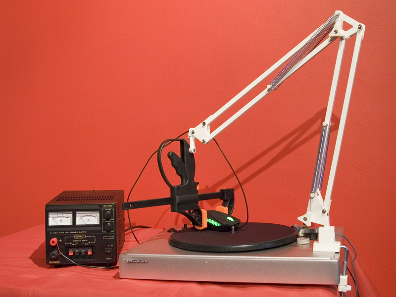
Maximum Speed Test
Interfacedevice benchtable
Acceleration 3 (velocity)
Acceleration is a term provided by some sensor manufacturers that indicates the maximum rate of change of velocity of the mouse that the sensor can detect, or how quickly it can accelerate from one point to another. Avago uses this term to define the maximum acceleration from a non-moving point. This benchmark is measured in units of g (acceleration of gravity) where 1g = ~9.8m/s/s (meters/second each second, also seen as m/s2).
It should be noted that this maximum level of acceleration is a very extreme amount and may be impossible to physically produce at 8g or more. As an example, in order to reach 15g acceleration your mouse would need to accelerate constantly from 0 to 5.1m/s all in the span of ~35ms.
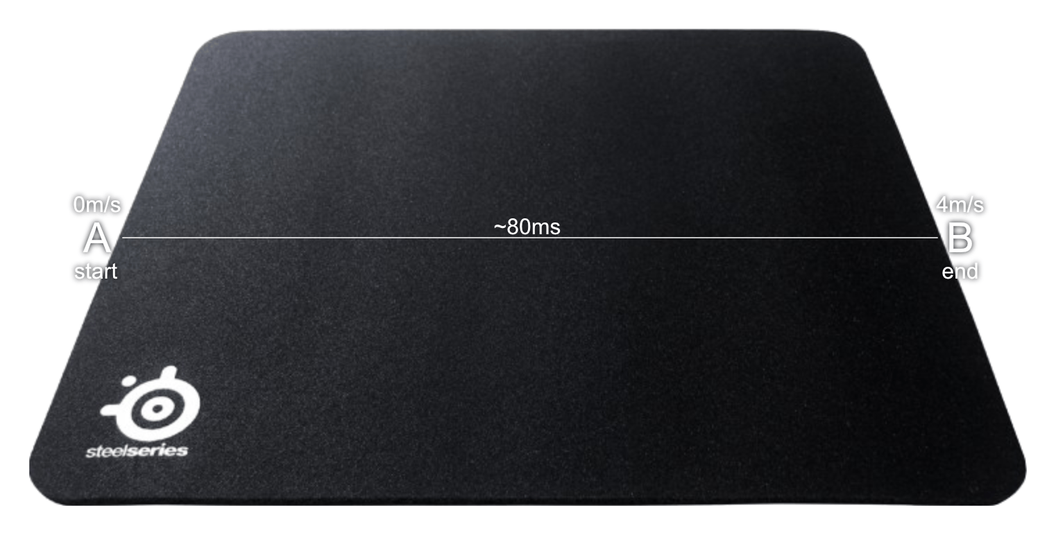
In a more realistic example, though still somewhat extreme, if we were to accelerate constantly from point A to point B, beginning at 0m/s and ending at 4m/s, where points A and B are the edges of a qck mousepad (320mm wide), all in the span of ~80ms, we would have achieved 5.1g acceleration (80ms is roughly the time that it takes to travel across a qck mousepad when traveling at a constant 4m/s).
Angle Snapping
Angle snapping (the term used by Avago), drift control, prediction, or any other name that has been coined in the last decade or so are all terms used to describe a type of path correction algorithm that can be found in the SROM of the mouse sensor (in most cases). The original purpose for including set amounts of moderate correction by many early sensor manufacturers such as Agilent (now Avago Technologies) was that by giving the sensor the ability to follow a path that the end-user could essentially be assisted in drawing straight lines. It should be noted that when this algorithm was first introduced in the late 90's (as an unlisted feature), that it was not included from a need to correct performance or stability issues.
There are a few ways of applying this type of path correction. In a more traditional method, when the SROM is loaded into the sensor it contains an unalterable amount of correction that is simply applied onto the Δx/Δy values determined by the DSP (also applied by the DSP). In a second method, the amounts of correction are still loaded onto the sensor via the SROM, but is controlled at the MCU in either enabling or disabling this path correction (this second method can be found in the G9x). In mice such as the Xai and Sensei, a third, more adjustable method of applying this path correction is used. The SROM of these mice do not contain any path correction, but rather the MCU in this case specifically (it could also theoretically be the DSP), calculates and applies a variable amount of path correction onto the Δx/Δy values based upon settings that the user chooses in their driver software (known here as FreeMove).
In any of these methods where angle snapping is enabled, actual movement ranges from ±(x number) degrees from the x or y-axis will be snapped to the closest axis. For example, if the sensor tracks movement at ±2 degrees from the x-axis where the deviation threshold is ±5 degrees, the output motion data will be snapped to the x-axis at 0 degrees.
The preference for using, or not using a mouse with moderate amounts of path correction is more of a preference/enthusiast factor rather than actual performance considerations, as this has largely to do with how well you can adapt to a certain kind of mouse or sensor over a period of time.
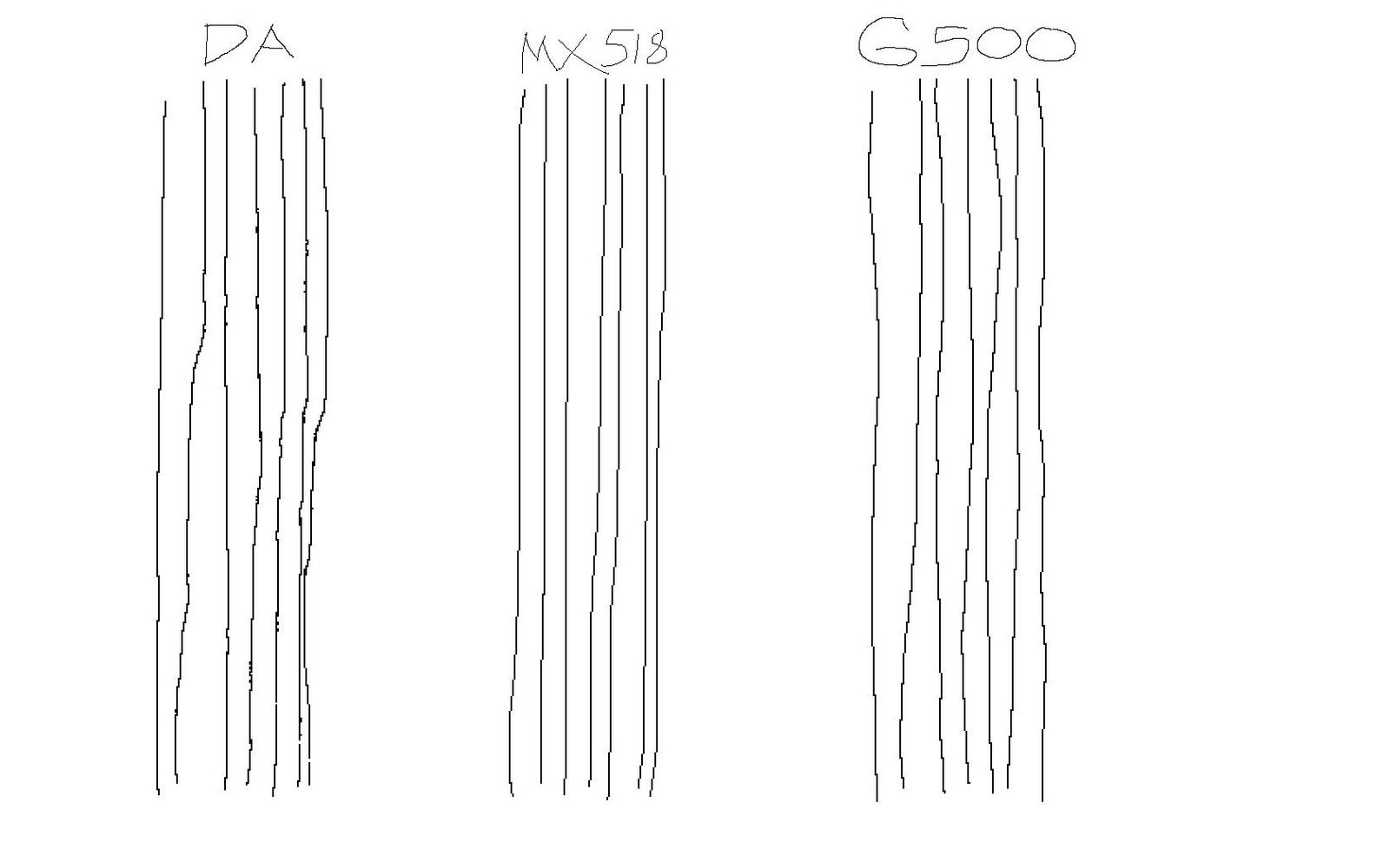
Testing your mouse to see if it has angle snapping is as easy as drawing lines in MS Paint at a medium speed using the pencil tool. The more imperfect the line, the less correction the mouse has. You can see in the image below the difference between the amounts of correction in the WMO1.1a (unconfirmed, possibly none) and moderate amount of correction in the MX518, both of which have been used extensively by professional gamers.

Polling Misnomer
There has been a slight misconception in how the polling rate of a mouse is able to influence the amounts of path correction that a user experiences. This type of path correction is applied (onto the Δx/Δy values that the DSP has determined) either at the DSP of the sensor, or at the MCU (depending on the implementation) before the data is translated into USB or PS/2 signals and sent to the host, and therefore cannot be influenced by the USB's polling rate.
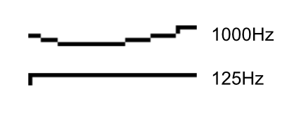
A low polling rate may look like "path correction" when you draw in Paint but it doesn't actually affect where the pointer lands in the end as 125Hz and 1000Hz still represent the same movement of your hand on the screen, whereas angle snapping influences where the pointer lands.
The following is a modified example from Bullveyr of a traditional setup, where a set amount of path correction is loaded onto the sensor via the SROM, and is applied by the DSP before it is sent to the MCU.
Let's say your mouse runs at 125Hz and the current data sent to the PC consists of Δx = 40 and Δy = 2. At 1000Hz this data package would be split into 8 packages, which could look like this:
x = 3 | x = 4 | x = 5 | x = 5 | x = 6 | x = 6 | x = 6 | x = 5
y = 0 | y =-1 | y =-1 | y = 0 | y = 0 | y = 1 | y = 1 | y = 2
In both cases the overall Δx/Δy = 40/2 and your cursor/crosshair will end up at the same position, although at 1000Hz in Paint the line would look less straight than the line at 125Hz (with two steps down and three steps up).
Because this implementation of path correction is done at the sensor level, the sensor still reads a Δx/Δy = 40/2 but may send 40/0 to the MCU (actually more like 20 times Δx/Δy = 2/0) and you would end up drawing a perfectly straight line. So with angle snapping you would actually end up 2 pixels below the point that your hand movement represents.
This is why a higher polling rate is smoother and more "precise" and looks less corrected, at least in Paint, but over a longer time period (long in the sense of 8 milliseconds) it doesn't affect the position of your cursor and doesn't affect the path correction algorithm.
CPI (Counts per Inch), Player Sensitivity, and Game Environments
Often confused with the term DPI (a measure of spatial dot density used in printing), CPI or counts per inch is an expression of the number of units (known as counts) that will be reported by the mouse when it is moved one inch (also formerly known as PPI, or pulses per inch). The higher the CPI, the higher the number of counts that will be reported in one inch and therefore the more movement of the mouse cursor that will take place. Additionally, the higher the maximum CPI of the sensor, the higher the maximum velocity that the sensor can report.
CPI resolutions can be either native or interpolated, where interpolated settings are resolutions not native to the mouse sensor. See the Interpolation section for a more in depth analysis of how interpolation theoretically could work. It should also be noted that the Windows sensitivity multiplier when not at the default setting (6/11) will change the number of counts registered by the operating system. See the Windows Sensitivity Settings section for more information.
When mouse manufacturers use the terms DPI or PPI they are referring to the CPI of the sensor. These terms have all been used relatively interchangeably by mouse manufacturers and consumers though CPI should be used as it is the technically correct term.
CPI and Player Sensitivity
So the practical question becomes, How much CPI does a person need? The answer is "it depends" as this largely hinges on how you control your mouse, what settings are used, and what type of games that are being played. To better understand what this question is asking a number of things should be discussed.
Because movement in a two-dimensional planar environment such as a desktop, or real-time strategy (RTS) game is represented by pixels, at some point we can no longer benefit from more CPI in because we have a bottleneck, the screen resolution. In a three-dimensional coordinate system such as a FPS where pixels have little or no correlation to movement this bottleneck is somewhat different, though there is still a limit to how much CPI can be used effectively (see "CPI and Sensitivity in an Inverted World Transform Matrix").
In both of the above systems, the amount of overall space we want to control our mouse in helps to determine what CPI resolutions will be useful, and at what point certain resolutions may become unhelpful to the player. These distances change depending on individual gamer preferences, the in-game sensitivity and CPI steps that are being used, and are generally grouped into three methods of low, medium, and high sensitivity players. These sensitivities are most commonly measured in distance per 360 degree rotation (in/cm/m), and while in a 2D planar environment a 360º rotation does not apply, the basic principles around how the mouse is controlled will.
Note: When changing styles or trying to determine your sensitivity, a period of at least 1-2 months should be allotted in order to fully acclimate to new settings, and not just a few hours. It should also be noted that some players can adjust their sensitivity style to suit the game they are playing and therefore may be more than one of these three types.
Low Sensitivity (high distance/360º): Avg control speeds of ~2.2m/s. Top control speeds of ~4.5m/s.
Low sensitivity players tend to use large mousepads as each movement of the mouse can travel considerable distances that require use of the entire arm. These distances range from around 21-40in (53.3-101.6cm) per 360º rotation. These players are also able to achieve very fast speeds of up to around 4.5m/s (177in/s) due to how they control their mouse.
High Sensitivity (low distance/360º): Avg control speeds of ~0.3m/s. Top control speeds of ~0.6m/s.
In contrast, high sensitivity players tend to operate their mice at much slower speeds, and usually use smaller mousepads as a result. These gamers rest their hand on the mousepad and have a central pivot/anchor area located at the carpus (bone cluster of the hand near the wrist) used for stability and control. Because of this behavior, they only tend to move around 3-10in (7.6-25.4cm) per 360º rotation. These players, because they move their mice much less when playing, tend to hit top control speeds of around 0.6m/s (23in/s).
Medium Sensitivity (med distance/360º): Avg control speeds of ~1.2m/s. Top control speeds of ~2.5 m/s.
Medium sensitivity players are somewhere in-between these two, and make up the majority of players. They either play on standard small pads or larger mousepads, whichever is more comfortable. Medium sensitivity players can also move their mouse quite fast at times achieving top control speeds of up to around 2.5m/s (98in/s). Due to how these players control their mouse these top speeds can vary considerably depending on how static their mouse position is and what games they are playing.
In order to find out what sensitivity style a player falls under, we need to determine what our real sensitivity is. This sensitivity indicates how much distance we will travel in order to complete a single 360º rotation and is dependent on a number of things, including our CPI resolution, Windows pointer speed, in-game sensitivity, and m_yaw/m_pitch values (angle of rotation per count, in degrees). We can approach this formula from two different angles depending on which variable is unknown.
i = 360 / (y * c * w * s)
c = i / (360 / (y * w * s))

i = real sensitivity (* 2.54 for cm)
y = m_yaw (default is 0.022)
c = mouse resolution (CPI)
w = windows sensitivity multiplier (6/11 = 1)
s = in-game sensitivity
It is important to understand that both the m_yaw and in-game sensitivity, as well as the CPI resolution allow players to use a wide range of settings to achieve their desired distance/360º. For instances where the m_yaw is the same, 1600 CPI + 0.5 sens, 800 CPI + 1 sens, and 400 CPI + 2 sens all represent the same distance/360º rotation, though due to the different CPI resolutions tracking will feel slightly different.
For the following two game environment examples, it is assumed that the Windows pointer speed is at the default 6/11, so that 1:1 tracking is maintained. Additionally for the first example following CS:S as a base, the m_yaw and the in-game sensitivity multiplier is assumed to be the default of 0.022 and 1 respectively (where applicable).
CPI and Sensitivity in an Inverted World Transform Matrix
How our player sensitivity and CPI are used in an inverted world transform matrix, or view matrix (the technical term for a camera based three-dimensional coordinate system) differs considerably from our two-dimensional desktop or a fixed perspective environment, such as those found in an RTS for instance. In order to understand what our CPI and player sensitivity means, we need to understand how this environment functions.
Perhaps the most important aspect of a dynamic coordinate based environment such as those found in an FPS is that movement is determined in radians, where 1 degree = ~0.01745329 radians (360º = 2π radians). This is done by taking each count of the mouse and assigning it a value in radians so that for each count of movement, a rotational turn of X radians will occur. If we assume default settings across the board (see above), each count will rotate the view matrix by ~0.0003839723 radians. It also should be noted that in this environment that it is the view matrix itself that moves while the camera remains in a fixed position (hence the reason why it is called an inverted world transform matrix).
As computer graphics are made up of vectors and our rotational movement occurs in radians, the unit that is most prevalent in computer graphics and displays, the pixel, has virtually no correlation to movement in this environment. The pixel through 3D projection only approximates the vectors and view angles of the view frustum (rendered area between the near view and far view planes of the camera) onto at two-dimensional screen. As a view matrix is also spherical in nature, this means practically speaking that pixels located at the center of our screen will represent larger angles than those at the edge of our screen from the projection process. Overall the pixel is the cause of much confusion when trying to objectively talk about aiming in this environment (see considerations).
How our field of view (FOV) functions is much like a real world camera based application, where adjusting the focal length of the lens will widen or narrow the view and either produce a more traditional or dolly zoom effect. For most FPS environments only the former will ever be present during actual gameplay. With the addition of widescreen aspect ratios, the FOV can be widened further and may behave like traditional wide angle lenses (in adjusting the entire picture), or simply add horizontal view or reduce the vertical view to the existing view screen. How this is handled depends on what type of widescreen method the game uses.
Other FOV Considerations
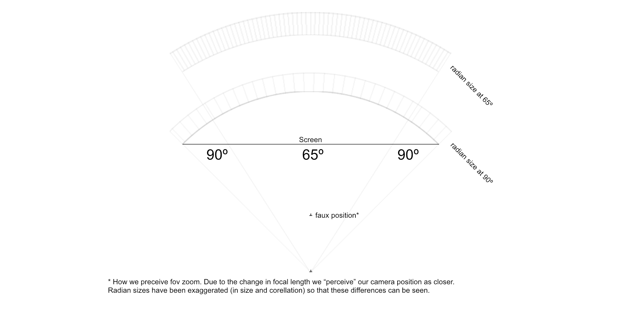
While the FOV determines how much of the world we see at any given moment and what pixels on the screen represent angle-wise, this variable, like pixels, also does not ever influence our sensitivity save for one circumstance. When games use the zoom_fov to adjust the FOV dynamically in game (for instance aiming down the sights of a weapon), an accompanying zoom_sensitivity variable (could be called anything) adjusts our overall sensitivity to another amount. The reason for this behavior is that the game engine, due to the view matrix being "closer" at least conceptually (not in actuality due to how focal length works), needs to scale the sensitivity so that in making a circular rotation, that our "speed" across this rotation remains constant. The resultant behavior is that the value in radians moved per count is adjusted by our zoom_sensitivity, depending on if we are "closer" or "further" from the transform matrix (shown below).
In order to find what these values are and how they differ from our normal sensitivity, we can use the following formula to get a rough estimate of our zoom_sensitivity. You can also find this formula here: http://kyto.dez.fi/ql/zoomsens/index.php
zoomsens = s * arctan(0.75 * tan(cg_zoomfov / 2)) / arctan(0.75 * tan(cg_fov / 2))

cg_zoomfov = zoom fov
cg_fov = default fov
s = in-game sensitivity
The above formula is specifically for Quake Live (modified id Tech 3 engine)
This formula also brings up the rather important question of what our field of view is in the first place. Unfortunately, knowing exactly what our FOV is (zoom_fov or otherwise) for each game can be rather convoluted, and in many cases be very difficult to %100 determine. There are two to three caveats that we must consider when attempting to discern these values: what scaling method the game uses, if there are multiple or dynamic changes in the FOV (as with zoom_fov mentioned above), and how the default FOV values correspond to scaling methods and the aspect ratio.
Scaling Method:
How a field of view is determined in modern 3D games changes based on each game, and the in-game aspect ratio with certain implementations. The three most common methods of Horizontal Plus (HOR+), Anamorphic, and Vertical Minus (Vert-) calculate a FOV slightly differently. In HOR+ a wider aspect ratio will result in a wider horizontal FOV (hFOV), where 16: 9 > 16:10 > 4:3 > 5:4. In a slightly different approach, an Anamorphic FOV will remain the same across all screen resolutions, and often image stretching or letterboxing (black bars on the top and bottom of the screen) will accompany this method where the FOV and monitor screen resolutions do not match. Another method of Vert- appears as well, where the vertical component of the FOV will be decreased when on a widescreen monitor with a widescreen resolution.
Differences in FOV:
In more modern games, such as Modern Warfare 2+3, the default FOV is not 90º, but another value (the aforementioned games default is 65º). This default value represents the FOV either from a 16: 9 or 4:3 aspect ratio, and is usually chosen based upon which platform the game is being primarily developed for (see "Aside: Why these FOV's are Chosen" for an explanation). Additionally in these games, we also have the ability to dynamically change the FOV according to if we are aiming "from the hip" (default), "down the sight" (ADS), or through a scope (MW2 uses zoom_fov for all the aforementioned cases). Finally, when "running" in games such as TES:V, Minecraft, and some others, the FOV will dynamically widen, again changing our values.
Default Value:
It should be noted that in the config or console for some games that this default value may appear as a fixed number, but the "real" or adjusted FOV may in fact be different or change depending on if the game uses certain scaling methods, what aspect ratio the default value is based on, and/or if a dynamic set of variables apply. For example, in HL2 the default value is 90º (a glitch between "Point Insertion" and "Red Letter Day" causes the console to report the default as 75º, which is incorrect); this default is a reference value and will not change despite altering the aspect ratio (4:3, 16:10, and 16: 9 are all "90º"). However, because HL2 uses HOR+, the FOV value reported in the console (in this case specifically, but not always) will not correspond to the "adjusted" FOV that the user will see when using widescreen resolutions. This is because the HOR+ method calculates these adjusted values in real time (frame to frame), using the default as a reference value in adjusting to the wider aspect ratio.
Additionally, while the adjusted value may or may not be reported correctly, there is still one variable that we haven't discussed that drastically alters what these values potentially are; what aspect ratio the default value corresponds to. Unfortunately this is the largest grey area, as there is no easy way of determining this correlation save for perhaps delving into the source code, or getting an answer directly from the developer. Some educated guesswork may result in the correct values, but cannot be considered %100 accurate in most cases (in games released before 2003 however we can safely assume that the default FOV corresponds to a 4:3 aspect ratio as widescreen monitors only first appeared around this time). It is for this reason alone that much of how our FOV is determined should be taken with a level of skepticism... Now we can present a theoretical example.
If we assume that the default value corresponds to a 4:3 resolution, a hFOV of 100.3º on a 4:3 resolution in theory will represent the exact same hFOV as a 16:10 resolution where the default or reference value is 90º. This is somewhat perplexing because in order to calculate (or find) the adjusted hFOV based on your aspect ratio, you need to be aware that the console in this case may only be reporting the default value, and not the adjusted value. The series of images below shows the comparison in FOV between these aspect ratios (4:3 » 16:10 » 16: 9).
To find out what scaling method your game uses, and what your FOV should be based upon the game being played, see the WSGF FAQ, games list, and the FOV calculator.
Aside: Why these FOV's are Chosen
To understand why certain games use a certain FOV we should briefly discuss the basics of why developers choose these values in the first place. The reason that games developed for consoles will always result in a smaller FOV than those developed for the PC has to do directly with our focused and peripheral vision. The human eye can see around a 150º field of view, but only approximately 60 degrees of that is in focus (due to a high cone density around the fovea centralis) while the remaining area is what we call peripheral vision (high rod density in this area). This vision while unfocused is still able to detect motion very easily.
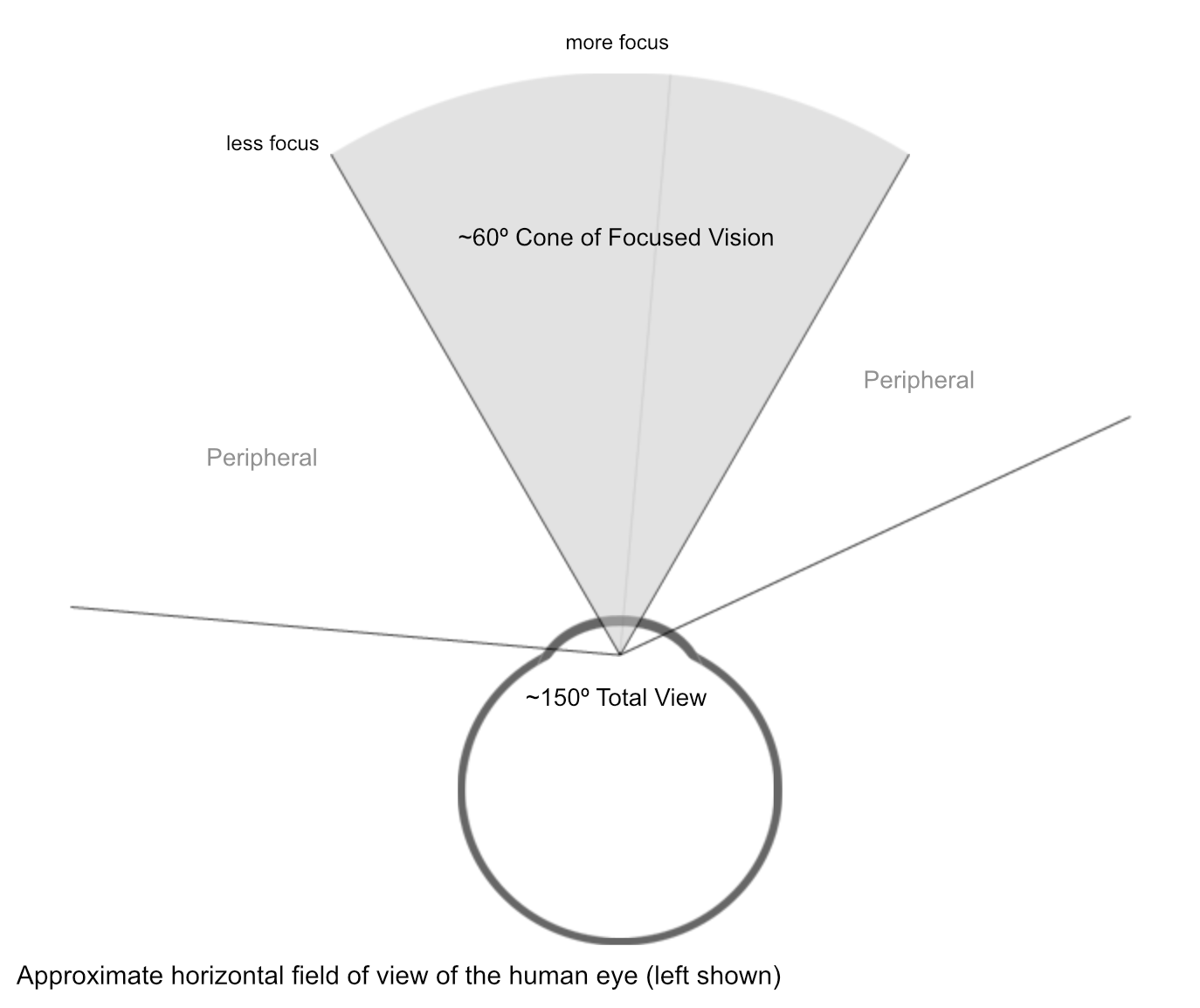
Because console games are specifically designed where the display is much further from the player than in a typical PC setup, the FOV does not have to be as wide due to the entire display falling into our cone of focused view (peripheral vision will not be used in a console setting, but will in a PC environment). When games are developed cross platform however, sometimes these FOV translations do not adjust to the optimal FOV in a PC gaming setting; this is where many of the current display issues or concerns arise (overly narrow FOV angles, and headaches or motion sickness from distorted, narrow, or stretched FOV's are the most commonly purported though more empirical data is needed for the latter consideration. Also see Simulator Adaptation Syndrome for other matters regarding simulators).
As with the above example of MW2, because the default FOV is locked at a lower value of 65º, when viewing the display at a much closer distance the image will appear stretched because our perceptual vision identifies our cone of focus to be out of place (in this case it is displayed much larger than it actually is in the real world). A rough overview of these considerations in games can be found here (Part I, Part II).
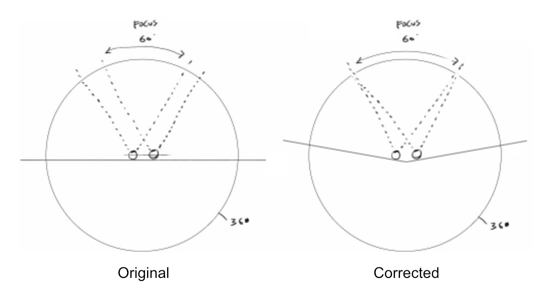
It should be noted that some of the presented data and FOV values that are purported in these two videos are slightly incorrect. For example, in HL2 the default FOV is 90º while the visual representation of binocular vision does not operate in this manner. Not only is our total FOV not 180º but the diagram suggests that each eye has an independent (and parallel) focal point from the other; this is not the case as human vision is slightly angled inward having single focal point that helps to both adjust focus and produce three dimensional depth. This diagram would have to be modified to look more like the image below in order to be correct.
Pixel Considerations
Now that we have examined how the environment works we can discuss how the pixel relates to our view matrix and aiming. Perfect pixel accuracy is something that has been talked about with great frequency, and unfortunately a topic where at least one or more problems occur, at least conceptually speaking.
The main problem area usually that arises is how pixels relate to movement and aiming in our view matrix. Because our FOV is constantly adjusting around our line of sight, we only ever have to account for coordinates adjacent to what could be called our center matrix (coordinates directly adjacent to our current coordinate). This could be roughly translated to pixels meaning that the only pixels that we ever have to concern ourselves with regarding movement and aiming are those directly adjacent to one another in the center of our screen (center matrix of pixels). However, as the translation of our view frustum onto a two-dimensional plane and radial movement are completely different functionally speaking and produce entirely different radial values for each unit, "pixel accuracy" is something that we only have to take into account in determining the maximum sensitivity possible before we start to "skip" pixels.
It is important to remember that this entire exercise is predicated on the idea of precisely aiming at pixels, which have a loose relationship to movement in this environment (perceptual correlation only).
The idea of pixel skipping is an imperfect translation of the following behavior. Normally our count radian value (radians per count of movement) will be far smaller than our pixel radian value (radians per adjacent pixels in our center matrix). This means that for each count of movement that occurs our view will rotate in a smaller radial amount than what one pixel represents. The approximate correlation of these two units is shown below.
![]()
There is a point however where a higher sensitivity ends up with our count radian value being larger than our pixel radian value. Beyond this setting every count registered by the OS will end up in a radial movement that is larger than what a single pixel represents (in the center matrix), and could look like pixel skipping, at least perceptually. It is important to remember that because we move in radians that we may be moving to a coordinate that is at the edge of the adjacent pixel (coordinates being infinitely smaller than a pixel) which could feel like an odd behavior to the player; but again, this is a perceptual incongruity as these values do not directly interact with one another %99 of the time (only when 2D planar movement is injected into this environment will pixels and counts have any direct correlation). The three variables that have influence over this ratio is our Windows sensitivity, in-game sensitivity, and m_yaw. If WM_INPUT (raw input) is being used, only m_yaw will be a pertinent value.
In order to make sure that your radial movements will be less than a pixels radian value, we can use the following formula, which will calculate the maximum sensitivity before this "skipping" occurs. We can also use a second formula to find our maximum m_yaw/m_pitch values for a given sensitivity before we start to "skip pixels". It is not recommended to set you sensitivity or m_yaw/m_pitch to these values as lower ones will allow for greater precision, however if your current settings are considerably lower it may suggest that you could benefit from a higher sensitivity.
b = (360 * tan(f / 2)) / (pi * g * y)
y = (360 * tan(f / 2)) / (pi * g * s)

b = maximum sensitivity
f = fov
g = screen resolution width
y = m_yaw
Additionally, we can calculate some of these sensitivity values based upon many common horizontal resolutions, m_yaw, and FOV values. These sensitivity values are also calculated from the angle represented by "the center" (max), "the average", and "the edge" (min) pixels for different settings:
Hor_res / m_yaw / FOV / max_px sens / av_px sens / min_px sens
640   0.022   90    8.139         6.392    4.076
800   0.022   90    6.511         5.114    3.260
1024      0.022   90    5.087         3.995    2.546
1280      0.022   90    4.069         3.196    2.036
1366      0.022   90    3.813         2.995    1.908
1400      0.022   90    3.721         2.922    1.862
1440      0.022   90    3.617         2.841    1.810
1600      0.022   90    3.255         2.557    1.629
1680      0.022   90    3.100         2.435    1.551
1920      0.022   90    2.713         2.131    1.357
2048      0.022   90    2.543         1.998    1.272
2560      0.022   90    2.035         1.598    1.018
The "center pixel" means pixel next to the crosshair, calculated using method from funender.com. The "average pixel" is calculated using method from ESR. The "smallest pixel" is at the edge of the screen.
Useful CPI
So two considerations about CPI can be gleaned from all of this information. Firstly, we can see that our CPI only determines how much distance we will travel to achieve a full 360º rotation, and can only be influenced by the Windows sensitivity multiplier (in how many counts are registered by the OS per inch). The other consideration is that we can therefore assume as the value of a count is a constant, that a theoretical "maximum useful" CPI could be determined with regards to our "pixel skipping" behavior. As the following is again a somewhat dissociated exercise, much of the information presented only loosely correlates to our actual movement.
Determining our maximum useful CPI with regards to "pixel perfect" aiming is dependent on two factors, how small of an area we can precisely control our cursor in, which we'll refer to as our minimum control area, and the radian size of our adjacent pixels in our center matrix. Unfortunately, as we don't have any studies to objectively determine our minimum control area we can only make an educated guess as to what this value might be, though we can assume that it will vary slightly from person to person. As FPS aiming needs to be more precise as we are generally aiming at objects much smaller in size, and as radial movement works very differently from pixel based movement, we can also infer that our minimum control area will need to be smaller than the control area for an RTS for example.
If we assume that we have perfect conditions regarding sensor tracking, 1:1 movement, surface uniformity and performance, etc..., the number of counts within a specific distance should look exactly like this:
Resolution / Counts in 250µm (0.25mm) / 125µm  / 62.5µm / 31.25µm / 15.625µm
200 CPI      1.96                       0.98     0.49     0.24      0.12
400 CPI      3.93                       1.96     0.98     0.49      0.24
800 CPI      7.87                       3.93     1.96     0.98      0.49
1200 CPI     11.81                      5.90     2.95     1.47      0.73
1600 CPI     15.74                      7.87     3.93     1.96      0.98
2000 CPI     19.68                      9.84     4.92     2.46      1.23
2400 CPI     23.62                      11.81    5.90     2.95      1.47
2800 CPI     27.55                      13.77    6.88     3.44      1.72
3200 CPI     31.49                      15.74    7.87     3.93      1.96
3600 CPI     35.43                      17.71    8.85     4.42      2.21
4000 CPI     39.36                      19.68    9.84     4.92      2.46
4400 CPI     43.23                      21.61    10.8     5.40      2.70
Using the formula for maximum sensitivity above, if we were to assume our default sensitivities, a screen resolution of 1920x1080, FOV of 106.2º (assuming 90º default at 4:3), and minimum control area of 62.5µm (arbitrarily amount, but very small), we can roughly work out that our maximum useful CPI for "pixel perfect" aiming will be only around 1400. If we were to further constrict our minimum control area to a more precise 31.25µm (1/32nd of 1mm), our maximum CPI doubles to around 2800. With a 90º FOV these values would be around 1100/2200.
Oddly enough, as the radian size of the center pixel matrix increases we have a larger margin of error when talking about pixel perfect aiming, and therefore we see a somewhat peculiar behavior in that smaller screen resolutions (assuming the FOV stays constant) give us the ability to be pixel precise with higher CPI values. As with the above example, on a 1920x1080 monitor we can only be pixel precise with 1400/2800 CPI depending on the size of our arbitrary control area. On a 1280x720 monitor, this CPI jumps to about 2200/4400 respectively. At the most outlying screen resolution of 3840x2160 (1080p x4) our values would be 600/1200.
What this shows is that the larger the screen resolution the less CPI we can be pixel precise with, as each pixel will represent smaller and smaller angles as resolutions get larger. This behavior is also inversely seen when we adjust the FOV to wider angles, as this will again increase the size of our pixel radian and therefore allows us to be pixel precise with larger CPI values (similar to lowering the screen resolution as in each scenario the pixel radian value increases). We can also extrapolate from the above information that when our m_yaw variable is also modified to smaller values we see that again we can use more CPI, as in this case the size of our count radian has been decreased. It is for these reasons that the entire notion of being pixel precise is somewhat unhelpful when trying to determine how much CPI is useful in a view matrix.
Ultimately as we the user are aiming at objects that are represented by pixels on our monitor, these limits may suggest a relatively appropriate endpoint to how much CPI could be useful in a view matrix (and when our movement may begin to be perceived as behaving oddly). Beyond these overall settings we can still benefit from an increase in speed, though our ability to precisely aim at objects will begin to suffer considerably the further we get from these values.
Formula Clarity
As a final note, many people may be familiar with injx's formulas (many of which are used here), however the formula that he realized to find the estimated useful CPI so as to not skip pixels (r = (pi * g) / (i * tan(f / 2))) is often presented in a linguistically clumsy manner causing undue confusion. This formula, found on funender.com, ESR, and other sites calculates the amount of CPI that is necessary to retain the same distance/360º as our "real sensitivity" (i) when our maximum sensitivity (b) has been set in order to achieve "pixel perfect" aiming with each registered count of movement.
As an example, two players want to achieve the same distance/360º, say 51.9cm/360º (20.45in), but one of them wants to have "pixel perfect" aiming (B) while the other wants to retain unscaled radial movement (A). Both of these players also use 1920x1080 screen resolutions, a FOV of 90, Windows settings of 6/11, and do not adjust their m_yaw values (though player B could). In this instance Player A needs 800 CPI to achieve his desired 51.9cm/360º. Player B however has to set his CPI to ~294 in order to have the same distance/360º as player A. This is because player B's sensitivity multiplier has been set to ~2.7128 (and therefore his count radian value is much larger) so that he can achieve pixel perfect accuracy with each count of registered movement.
Useful CPI in 2D Planar Movement, or a Fixed Camera Environment
Thankfully for games with fixed or top down camera angles where angle based movement doesn't apply (such as in a RTS), these useful limits are far easier to discern due to our movements being recorded on a two-dimensional plane rather than in a view matrix. Because of this, the pixel becomes an important variable in discerning movement. The maximum useful CPI that a person can use in these instances is limited by the minimum area that a user can precisely control the cursor of their mouse, and is dependent on two factors: our screen resolution, and how large of an object is being selected.
As with the above example, we are assuming that we have perfect conditions regarding sensor tracking, 1:1 movement, surface uniformity and performance, etc..., If these conditions are met, our counts/pixels/distances should look exactly like this:
Resolution / Pixels moved in 1mm / Pixels moved in 0.5mm / µm moved in 1px
200 CPI  =   7.87                  3.93                    127
400 CPI  =   15.74                 7.87                    63.5
800 CPI  =   31.49                 15.74                   31.75
1200 CPI =   47.24                 23.62                   21.16
1600 CPI =   62.99                 31.49                   15.87
2000 CPI =   78.74                 39.37                   12.7
2400 CPI =   94.48                 47.24                   10.58
2800 CPI =   110.23                55.11                   9.07
3200 CPI =   125.98                62.99                   7.93
3600 CPI =   141.73                70.86                   7.05
Let's take an example of selection areas in the RTS game StarCraft 2, and let's say we want to be able to accurately select a single unit (larvae being the smallest unit); we first need to find out how large a selection area is. Because these games are still made up of vectors, the selection area will occupy relatively the same amount of space on the screen as long as the aspect ratio remains constant. As SC2 uses a perspective projection and not an isometric one, we also have to account for our depth of field, in that objects closer to the top of our screen will be smaller than those next to the UI.
Using our larvae example we can set the minimum, maximum, and median area sizes, where the median selection area will be the most predominantly used of the three. In figuring out how much of the screen these areas represent, we can roughly work out how this is represented at each resolution. You can see below the approximate diameter of the circle in pixels that this selection area represents.
![]()
minimum, median, and maximum areas
Larvae Selection Area (pixel diameter) by Aspect Ratio and Selection Area Distance (min, med, max)

16:10       (~%0.0002439 / ~%0.0003535 / ~%0.0004631)
 3840x2400   53.49         64.4          73.71
 2560x1600   35.66         42.93         49.14
 1920x1200   26.74         32.2          36.85
 1680x1050   23.4          28.17         32.25
 1440x900    20.06         24.15         27.64
 1280x800    17.83         21.46         24.57

16:9        (~%0.0002599 / ~%0.0003703 / ~%0.0004808)
 3840x2160   52.39         62.53         71.25
 2560x1440   34.92         41.69         47.5
 1920x1080   26.19         31.27         35.62
 1600x900    21.82         26.05         29.69
 1366x768    18.63         22.24         25.34
 1280x720    17.46         20.84         23.75
The third factor we need to consider is how small of an area are we able to precisely control the cursor of our mouse in. As this control area will vary from person to person, we will arbitrarily choose an extremely small area of 0.5mm (500µm), both to illustrate the precision extremes, and our optimal control example. It should be noted that the control area of 0.5mm is a very small area, where many users will not be able to precisely control their mice in this area due to its size.
Now that we have our selection areas, and our minimum control area, we are able to see the maximum amount of CPI we can use and not lose our ability to precisely control our cursor. As we have three values to work with, the data will be presented as a range with the median value in parenthesis (note that with an isometric perspective where a depth of field isn't applicable such as in SC:BW, only one value would be needed).
If we are playing on a resolution of 1920x1080 we can see that the maximum CPI that we can use with absolute precision is 1400-1800 (1600). Moving beyond this CPI range we will still gain cursor speed, but it will also result in an increasing loss of control ability. If we modified our minimum control area to a larger area of 1mm (still very small), we can see that our useful CPI has been significantly cut to between 600-900 (800). Similarly, if we retained our control area at 0.5mm and shrank our selection areas to 13.09 / 15.63 / 17.81, our maximum useful CPI has again been significantly cut.
Conclusions
From this example we can see that the estimated useful CPI in this environment is rather small when compared to our sensors maximum capabilities, with even the most outlying resolutions (3840x2400) only peaking at around 3600 CPI in the most lenient of situations. Of course, if we set our CPI within this range of values we will be working at the absolute minimum level of precision, therefore it is not recommended to set our values to satisfy this range as lower CPI steps will net us more precision.
It is up to the user to determine the balance between how much speed they need in their cursor movements, and how much control they need over their cursor, with the maximum speed and minimum control of our cursor converging at these estimated values. One interesting correlation can also be found in this data, in that the maximum amount of CPI that we can use in even the most forgiving circumstances will always be less than the pixel width of our screen resolution.
FPS (Frames per Second) and Pixel Resolution
Frames per second (sometimes seen as reports per second, or RPS) are the number of frames captured by the image acquisition system (IAS) of the sensor per second and are used to detect and calculate the Δx/Δy movements of the mouse. This capture frequency is usually a variable amount (exact amounts depend on implementation), but is typically in the thousands of frames. In Avago's popular ADNS-3080 sensor, this capture frequency will range from 2000-6500, where 2000 is the minimum amount. In the first generation of 3080s, the minimum capture frequency was 500. You can check the sensor specifications or datasheets to find out what the FPS of the sensor is.
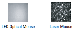
What a optical sensor captures vs. a laser sensor
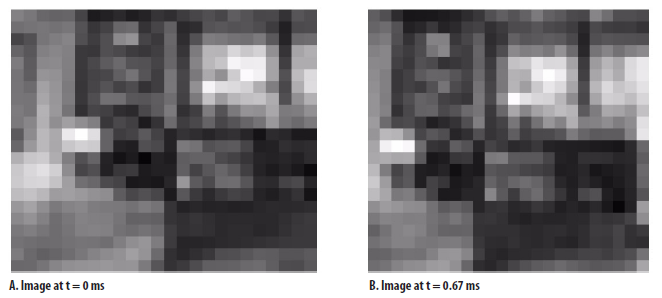
Two separate frames captured by the sensor giving the data it needs to calculate movement
In mice that use this image capture method, each frame is also taken at a specific resolution, known as its pixel resolution and helps alongside the FPS to accurately track the movements of the mouse. This information can usually be found in the datasheet of each sensor. In the ADNS-3080 as mentioned above, this image capture area is comprised of a 30x30 pixel matrix, and is represented below in Avago's datasheet.
![]()
Jitter/Ripple
Jitter, or ripple is a hardware error where single units of movement data gathered from the sensor deviate from their "actual" position during tracking, causing the cursor to behave erratically from time to time. This observed behavior occurs as a result of the sensor of the mouse being pushed to its limit. This error when present is usually more pronounced at higher CPI resolutions due to the sensor trying to detect accurate surface data at higher values.
A mouse that produces this error will show noticeable erratic movements when performing tests in MS Paint. Below are three images that show the effect of jitter on cursor movement in Paint. If you are unsure if your mouse is producing this error, simply draw in Paint with the pencil tool to see if you experience these errors. If your mouse acquires this error where the mouse did not have it originally, it may suggest that you need to clean your sensor cavity and/or mousepad.
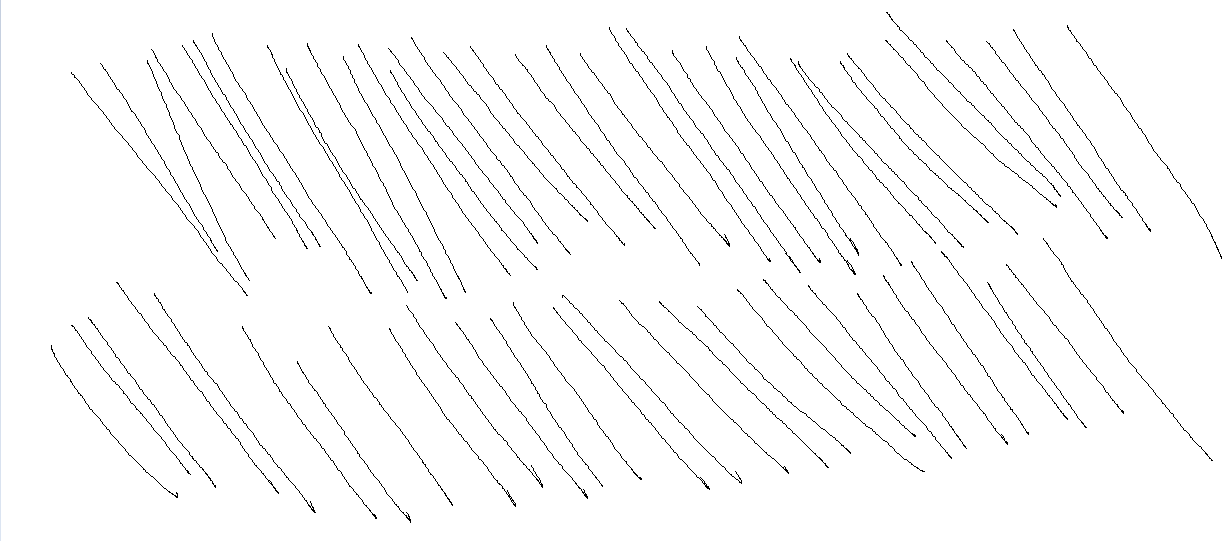
G9x at 1200 CPI, most likely on a cloth pad (unconfirmed)
Deathadder 3.5G with older firmware (circa 2010) on a PureTrak Talent
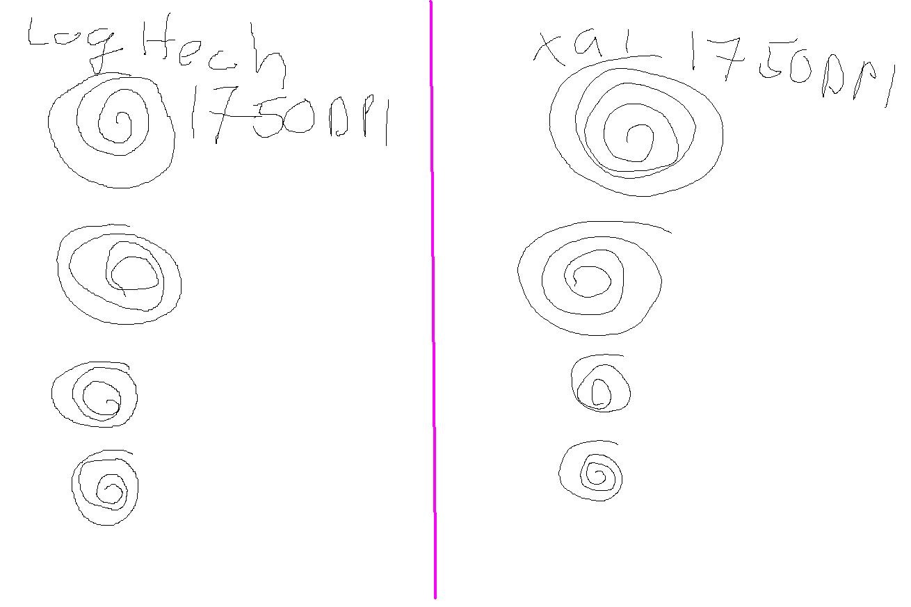
G100 at 1750 CPI
Certain mouse surfaces may produce or contribute to this effect regarding some mice, while not with others. Performance of the Zowie AM for example can be very mousepad dependent, as the cursor will jitter on a multicolored/multiple patterned mousepad while less so on a pure black mousepad (Source). The Abyssus has also been known to be somewhat finicky, producing this error when on certain pads (Source, see entire thread).
Jitter, or Ripple
It should be noted that Logitech refers to this error as "ripple" as there is another hardware error already termed "jitter". This type of error causes the mouse cursor to behave erratically with no physical input from the user (the size of these movements in most cases are much less than a single count or pixel, so they aren't usually visible). This type of error also relates in part to the "jitter tolerance" of the sensor, where this correction is designed to prevent the sensor from registering movement under a certain threshold (movement data would not be recorded by the sensor until it passed this threshold). If for example a sensor suffered from the above error but the jitter tolerance was high enough, the sensor may not register any movement even though this error is present.
Interpolation (Two Definitions)
Interpolation 1 (guestimation)
Interpolation or frame skipping, occurs when the MCU is forced to guess at the Δx/Δy values of the sensor instead of having the "real" Δx/Δy values. This can occur in one of two ways. If the sensor tracks values that are greater than its default range (neutral range) the MCU will be forced to guess what the actual Δx/Δy values are. Secondly, if the receiver clocks of the sensor and MCU are not in sync, or the service interval (known as frames in USB 2.0) returns an error, reset, or null data (through ESD events, invalid addresses, MCU firmware flaws, etc...), the MCU may again be forced to guess the Δx/Δy values.
Interpolation 2 (non-native resolutions)
CPI resolutions that are not native to the mouse sensor are commonly referred to as interpolated. Native resolutions are technically more precise, while interpolated resolutions could be nearly as precise, or very bad, depending on the implementation. As an example, in Avago's original 3080 sensor, the native CPI resolutions were 400 and 1600; often times 800 CPI (1600 halved) would be an interpolated resolution that the mouse manufacturer would additionally provide. Laser sensors have a distinct advantage in having many more native settings over their optical counterparts. The ADNS-9500 for instance can reach up to 5700 CPI (depending on firmware and lens, default is 5670) but is scalable in steps of 90 CPI, all of which are native (90, 180, 270, etc...). You can check the sensor manufacturers website (or datasheets) to ascertain if your CPI resolutions are native or interpolated.
Most of the time when you are using "less" CPI than what the sensor is capturing, there are two main ways of outputting those values to the host PC.
- Discarding a number of "counts" per every update sent to the MCU. In this case you might have great tracking at more or less still movements, since what gets discarded doesn't really qualify as a noticeable difference, but at high speeds it might feel like positive or negative acceleration.
- Keeping track of the "discarded counts" and adding them to the package that makes it to host, (possibly labeled as "correction" or "interpolation" by some). In this method you might experience some kind of "jittering" if the number of counts that arrive to the host PC is not enough, in that the MCU is hard-coded to update the registry every x number of counts instead of dynamically allocating it (that later could be the reason why the AM has that blocky movement when on 2300 CPI).
So interpolation per se, doesn't make much sense when talking about using less CPI than the native settings, as counts can be dropped. Interpolation at higher settings than then max CPI of the sensor (such as the "double counts" in the original Sensei) will however produce inconsistencies and should be avoided.
If a mouse manufacturer decides to go ahead with interpolation, which the mouse needs in real time (or at most, a very low time difference, preferably sub 1ms limit), there needs to be something such as a MCU with a good computational power so that it can output the result in far less than 1ms, else there may be a feeling of some input lag. This could be done by having a MCU that can output interpolated data of 1ms in less than 0.5ms (500µs) so that we could have a diagram resembling this:
Sensor:          |-|  |-|  |-|  |-|  |-|
Microcontroller:   |-|  |-|  |-|  |-|  |-|
Time (1ms):      |    |    |    |    |
- Sensor: The data that would be sent to the MCU to interpolate, which would have a delay of, in average, 0.5ms.
- Microcontroller: The time the MCU would use to interpolate the incoming data and send it over the USB interface, with a delay never bigger than 0.5ms.
- Time: Every update that gets sent to the computer (1ms if the polling rate is 1000Hz).
Then again, the above numbers are completely fictional, and can be done with a much more narrow timescale if the MCU used is powerful enough. Nowadays for some of these calculations you only need several nanoseconds with dedicated hardware, so you could process this data without any delay higher than what the processor can achieve, which is significantly shorter than even the largest USB transmission packet sizes.
IPS (Inches per Second)
Inches per second is a benchmark given by sensor manufacturers that somewhat reflects the perfect control speed of a mouse, where a PCS of 1m/s is ~39.4IPS. If a range is given (e.g. 60-120IPS) the lowest rating typically means that the sensor will track up to 60-70IPS without issues on most surfaces (roughly the PCS of the sensor), though the sensor can go beyond that granted you are using an optimal surface. These ratings may not be entirely accurate, but they give a rough idea of the maximum tracking rates of the sensor. See the Perfect Control Speed/Malfunction Rate section to better understand these ratings.
LOD (Lift-Off Distance)
The lift-off distance of a mouse is the height at which the mouse stops tracking on a surface. The lift-off distance of a mouse is especially important regarding tracking accuracy from users with low CPI sensitivities (high distance/360º, FPS gamers mostly) due to the constant lifting and repositioning of the mouse. Some tests will show the correlation between where a mouse begins to lose tracking capability, and when it completely stops. LOD is measured in millimeters and is easily tested by determining the number of CD's it takes where the mouse stops tracking (1CD ~1.2mm).
Provided the sensor opening is accommodating, many people have used tape fixes to lower the LOD of their mice. The fix puts non-transparent tape over roughly half of the sensor hole but makes sure the "eye" of the sensor is still uncovered. The idea is to reduce the intensity of the IR LED on the surface used. This will reduce the lift-off distance of the mouse, but will also reduce the maximum tracking speed of the mouse if done incorrectly (the correct way leaves the lens area completely free) The image below shows the tape fix correctly applied to a Steelseries Kinzu.
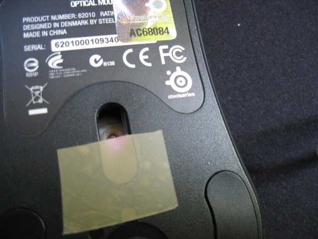
MCU (Microcontroller Unit)
A microcontroller unit (sometimes called a microprocessor, or MPU) is a small computer on a single integrated circuit containing a processor core, memory, and programmable input/output peripherals, and are found in all high end gaming mice. The main purpose of the MCU is to translate the data received from the DSP (or ASIC) into USB or PS/2 signals before they are sent to the host. The MCU can either be separate from or integrated into the sensor itself. In implementations where an external MCU is used, communication between the sensor and MCU takes place over a synchronous serial port, or SPI. Additionally, the MCU is also where the SROM is usually stored, CPI interpolation is processed, and where angle snapping is controlled, where applicable (see Angle Snapping section for clarification).
The process/communication between sensor and MCU will usually happen in the nanosecond range. For example the MCU in the Xai, the STMicroelectronics STM32-F103C8T6, is a 32-bit MCU capable of computational speeds around 72MHz (13-52ns range), while some 8-bit MCU's, such as Sunplus SPCP866E2A found in the G400 will operate around 16MHz (90-360ns range). In either case, the computational speed of the MCU is more than capable of keeping pace with the processing speed of the sensor.
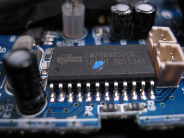
A typical look of an external MCU on the PCB
Microswitches
Microswitches are a basic switch in place to register button and wheel actuations of the mouse. These switches have a very small contact gap and snap-action mechanism, a contact structure that switches for a specified movement and specified force, and enclosed in a case with an actuator provided on the exterior of the case. Basic switches are mainly comprised of five components, the case, terminal section, actuator, snap-action mechanism, and contact section (shown below).
The three most common manufacturers of microswitches for mice are Huano, Omron, and TTC (Trantek). Of these three, Huano switches provide more tactile feedback and require slightly more force to activate than Omron or TTC switches, while Omron switches tend to have many more gradations of activation force and tactile feedback than either Huano or TTC. Much of how a microswitch feels is also largely dependent on the build quality of the mouse, with the shell and switch actuation design playing a large role alongside the type of switch being used.
The type of switch that a user prefers is a entirely preferential (much like mechanical keyboard switches), however, for those who are looking to swap out their microswitches an excellent guide can be found on Swapping Microswitches for Dummies.
Further information on basic switches can be found on Omron's website.
Perfect Control Speed/Malfunction Rate
Perfect control speed (PCS) and malfunction rate (MR) are two terms that were coined by the professional Quake player and user Sujoy Roy on ESReality when working on his now well known Mouse Score evaluation in 2006 (see link below). These two terms were designed to express the general tracking precision and loss of precision in the various mice he tested.
Perfect control speed is the fastest speed at which the mouse can be physically moved where it performs exactly as it should. In contrast, the malfunction rate (sometimes called malfunction speed) is the speed beyond which the mouse loses all tracking accuracy. Once you move beyond the malfunction rate, the cursor movements may no longer correspond to the mouse movements of the user as anything can happen. The perfect control speed/malfunction rate of a mouse is measured in m/s while sensor manufacturers have begun in recent years to use other terms to express these benchmarks (IPS).
While these tests were groundbreaking at the time, they only accounted for the maximum CPI steps of the mouse (the highest at the time was 2700) and are only accurate for the CPI steps and mousepads they were tested on. For instance, the MX518 has a perfect control speed of 2.03m/s at 1600 CPI on a qck+; at 400 CPI the PCS was much higher, but because only one step was tested the data ended up being somewhat misleading regarding overall tracking performance. Today these tests should include both the surface that the mouse was tested on (e.g. PureTrak Talent), and a series of CPI values. For mice with fixed CPI steps, every setting should be tested. For mice that have adjustable CPI steps such as laser mice, popular "fixed" resolution settings should be tested (e.g. 400, 800, 1000, 1600, 1800, 3500, and the max CPI step). When performing various tests for the perfect control speed of the mouse, it is also important that these tests are taken at various polling rates as performance at 125Hz can differ significantly from performance at 1000Hz. When choosing these rates, at least 125Hz, 500Hz, and 1000Hz should be tested, or if the various polling rates are specified, every setting should be tested (much like the CPI step testing procedures). See the Polling Rate section for instructions on how to change your polling rate.
The type of sensitivity a player uses (low/med/high, see CPI, Player Sensitivity, and Game Environments) will greatly influence how these benchmarks will affect them. For instance, a low sens player (high distance/360º) needs to be able to track accurately at high speeds, and will benefit more from a high perfect control speed because their mouse movements will many times reach beyond the 3m/s range. In contrast, a high sens player (low distance/360º) may only ever reach speeds of 0.6m/s and therefore don't require a mouse with a high PCS.
The Enotus Mouse Test and outerspace's IPS Logger are both programs that can test the relative perfect control speed of your mouse. The Enotus Mouse Test is a standalone application, while outerspace's logger requires an audio software program such as Audacity, or Audition (original program used) as well as some math in order to interpret the data properly (the image below shows how this data is interpreted). Note that the precision and smoothness tests in the Enotus application do not function properly, so it is best to avoid them. These programs are not quite as accurate as the apparatus that Sujoy originally built, but they give an idea of the maximum tracking rates of the mouse. These programs can be found below:
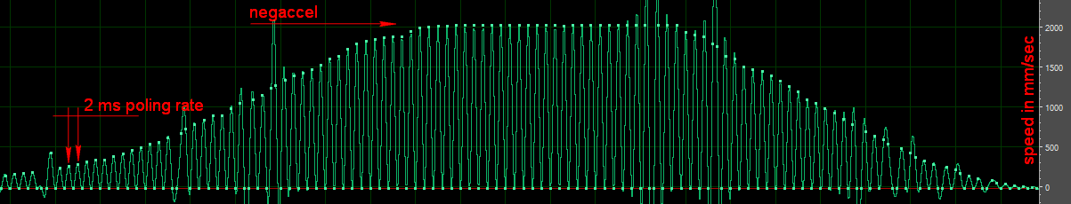
Mouse Shown: A4tech X-718BK at 1600 CPI (outerspace's Logger in Audition)
Polling Rate
Currently (see USB 3.0 addendum below), your mouse's polling rate determines how often it can send data to your operating system. All button actuations and Δx/Δy data must wait until the host initiates a poll for them. By default, Windows will poll a USB mouse every 8 milliseconds, or at a rate of 125Hz. You can increase an operating systems polling rate with a number of programs/drivers/registry fixes (see below). The purpose of increasing the polling rate is to reduce the bottleneck of the rate at which the mouse is capable of reporting data, and the gathering of this data by the host system. Increasing the polling rate has no effect on your sensitivity or the amount of path correction experienced by the user, but it will increase CPU usage.
Because the polling rate of a mouse is not constant, we don't know how often the often the device is being polled. This data is easily accessible however from either the Mouse Movement Recorder, Direct Input Mouse Rate, or Mouserate Checker programs. For example, if your mouse has a polling rate of 500Hz, you will reach this rate once you are moving at a constant of .04m/s, or 1.5in/s (very slow speed).
- Direct Input Mouse Rate Program
- Mouserate Checker
- Changing your Polling Rate
- Polling Rate Information (Funender.com
Data Transfer Process
Let's take a look at how the data transfer process works under the current USB 2.0 specification (soon to be phased out). This example will assume that our mouse setup uses an external MCU in communication with the sensor. The polling rate of the host can be broken up into frames, for USB 2.0 this will mean either full-speed frames, or high-speed micro-frames. For devices with a 1000Hz poling rate, or 1ms, every poll is represented by a single full-speed frame, or 8 micro-frames (image below).
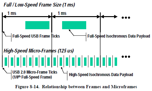
Each of these frames contain a number of data transactions with up to 3 interrupt transactions per micro-frame (all keyboards and mice use the interrupt transaction protocol in communication to the host). This means that in 1ms of time, a mouse is able to report up to 24 data packets to the host if using a continuous burst mode, which is not possible in the current USB 2.0 spec.
This data is first collected from the sensor IAS and processed by the DSP (see A Short Overview of Mouse Sensors for PTE differences), then read by the MCU through the SPI. This data is then combined into one package and translated by the MCU into USB or PS/2 signals, and then sent back to the host. The MCU will only gather this data from the sensor when the host controller initiates the request, or in other words, the MCU will not collect any data without explicit instruction to do so from the host system and is why 1000Hz is the current maximum speed at which this data can be gathered (the MCU will still gather this data in micro-frames but has to package/transmit them in full-speed frames, or 1ms frames).
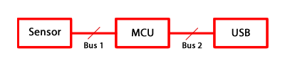
You can begin to see why the default rate of 125Hz is somewhat undesirable. If your USB and mouse only had a 125Hz polling rate, there would be between 64-192 packets of data that will have been crunched into a single packet by the time it reached the host controller.
So now let's take a closer look at the interrupt transaction protocol and how it functions.
Interrupt Transaction Protocol
Each data transaction consists of three main sections (Token/Data/Handshake), plus the SYNC and reset conditions. First the device and host receiver clocks must synchronize, then the data packet can be processed, followed by a condition that resets the bus so that this operation can then be repeated, or return to an idle state.
---- idle ---- [ Sync | SOP ] [ Token | Data | Handshake ] [ EOP ] - [ Reset ] ---- idle ----
The SYNC field precedes each packet to allow the receiver(s) to synchronize their bit recovery clocks. Part of the SYNC field is the start of packet (SOP) delimiter which announces the beginning of a packet to the controller.
At the beginning of the packet is the token packet which determines whether the communication will be host to device (known as OUT) or device to host (known as IN). The data packet is where the data is contained, and is anywhere from 8 to 1024 bytes depending on if the device is low, full, or high-speed. The handshake packet is used to report if data will either be acknowledged (ACK), or generate an error.
NAK (not ack) - The receiving device cannot accept the data or transmitting device cannot send it.
STALL - The endpoint is halted, or control pipe request is not supported
NYET - No response yet from receiver (high-speed only)
At the very end of the main portion of the packet is the end of packet delimiter, which again simply announces the end of a packet to the controller. Below is the dataflow overview of the interrupt transaction format (EOP not shown):
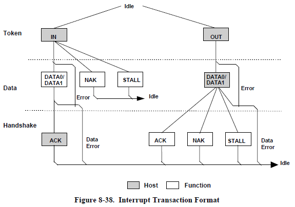
The final step is the reset. When the host wants to start communicating with a device it will start by applying a "reset" condition which sets the device to its default unconfigured state (e.g. idle). The same "reset" condition is applied for when packets are complete and need to return to their idle state.
All of these steps take place in the span of a single transaction, which could be as short as 5.2 µs (microseconds). Occasionally clocks may not be fully synchronized which is where errors may occur.
A Special Note on Future USB Specifications
The USB 3.0 specification dramatically changes the way that a host and HID-devices communicate. The basic data flow and transfer concepts are preserved, while some packets or specifications have been integrated or removed entirely. A few notable changes in dataflow should be mentioned.
A dual simplex connection is now being used which allows packets to leave and arrive simultaneously; these transfers are also no longer serial in nature (where packets must finish before the next begins). SOP packets have been replaced by isochronous timestamp packets (ITPs), while token packets have also been removed (IN is replaced by the handshake packet, while OUT has been incorporated into the data packet). SuperSpeed USB also supports continuous bursting for all types of functional data transfers, unlike USB 2.0. Also note that in the USB 3.0 specification *continuous device polling has been eliminated* and has been replaced by asynchronous notices.
This last note is of particular importance as each device now sends data when it is recorded; it is still host controlled, but in a different way that no longer limits packet sizes. A SuperSpeed interrupt can move up to three maximum sized packets per service interval (125µs, formerly known as a micro-frame), meaning that the maximum theoretical rate at which data can be received by the host is every 41.6µs, the equivalent of a 24000Hz polling rate in USB 2.0 terms*. The size of a service interval (125µs) represents the minimum theoretical rate of data transmission, or what would roughly equate to a 8000Hz polling rate in USB 2.0 terms*.
**The non-serial nature of USB 3.0 makes these translations an inexact correlation, but an idea of the increase in transmission speeds can be seen through these estimations.*
SROM
Secure read-only memory, or SROM is a class of storage medium that contains and distributes the firmware files of the mouse. These firmwares are an ASCII text file with each 2-characterbyte (hexadecimal representation) on a single line. The mouse's SROM is commonly stored on the MCU (Avago sensors operate in this manner, though not all sensors/mice have to) and internally controls how the sensor operates (what registers can be accessed or written to, how much CPI and how many CPI steps are used, how angle snapping functions where applicable, etc...). Each time the mouse is connected to a power source, the SROM is loaded into the sensor (through the SPI if externally housed).
It should be noted that some mice have the ability to flash this firmware when newer ones are released to address certain errors or overall performance improvements, while others cannot. Newer firmwares may improve upon certain areas while others are slightly modified (or compromised). In firmware updates to the CM Spawn for example, 30a may produce better tracking on lighter surfaces while 31+32 have a much lower LOD, though v32 isn't exactly optimal as IPS and cursor quality goes as it is a compromise for the sake of a lower LOD (Source). Newer beta firmwares 60+61 address a number of issues (61 specifically also remedies an angle snapping mix-up found in 60) including the perfect control speed, LOD, and overall tracking performance ([_Source, page 6 onwards*_). Note that incorrectly flashing your firmware may result in a bricked mouse, so *do so at your own risk*.
Windows Sensitivity Settings
In Windows, the pointer speed setting determines how the operating system interprets raw mouse input (found under mouse properties in the control panel). In order to achieve perfect tracking or a 1:1 ratio, the default setting of 6/11 must be used (shown below), no other notch will produce 1:1 tracking. It is important to note that this ratio refers to 1 count of raw mouse movement being registered as 1 count of movement by the OS (raw count: registered count). The common misconception is that a 1:1 ratio will mean that 1 count = 1 pixel, which is accurate for 2D planar movement, but only coincidentally so as the pixel is the smallest unit of movement in this setting (important for understanding FPS movement, see CPI, Player Sensitivity, and Game Environments).
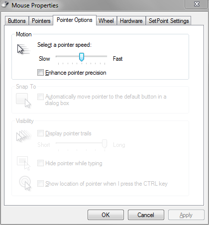
Windows 7 Mouse Properties Pane
Pointer speed settings above the default 6/11 notch are considered very inconsistent and also cause unit skipping, and therefore should not be used. This is very important for 2D planar movement as these settings will cause inconsistencies and pixel skipping. In a view matrix this skipping behavior is theoretically less of an issue due to movement occurring in radians (see CPI, Player Sensitivity, and Game Environments), though inconsistencies will still be very apparent and should be avoided. Most settings under 6/11 while useable (excepting 5/11 which has some inconsistencies) are less desirable than 6/11 as they cannot produce 1:1 tracking. Below are the multipliers for each setting and their general performance output:
1/11  = 0.03125 (ok)
2/11  = 0.0625  (ok)
3/11  = 0.25    (ok)
4/11  = 0.5     (ok)
5/11  = 0.75    (every 4th count is ignored = inconsistent)
6/11  = 1.0     (optimal setting)
7/11  = 1.5     (every 2nd count registers as 2 counts of movement = inconsistent + unit skipping)
8/11  = 2.0     (unit skipping)
9/11  = 2.5     (inconsistent + unit skipping)
10/11 = 3.0     (unit skipping)
11/11 = 3.5     (inconsistent + unit skipping)
Because the base unit of movement is a count and its value therefore constant, those values registered by the OS that are not integers will be ignored until the nearest integer is reached. It is due to this constancy that a skipping behavior occurs in the first place. In cases where the value of a raw count of mouse movement is not registered as an integer, these fractional values are stored by the OS until it registers enough data to move by one unit. In regards to settings above 6/11, these fractional values are stored and applied alongside the already reported integers which is why 7/11, 9/11, and 11/11 are additionally inconsistent as every other raw count of movement produces a fractional value.
Optimal Sensitivity
The optimal way to obtain the desired mouse sensitivity for a user would be to: (1) leave the slider on the default setting (6/11), then (2) tweak the CPI of the mouse until you have found your perfect sensitivity. Regarding mice that have fixed CPI settings (e.g. 400/800/1600), the next step after finding the closest CPI would be to (3) tweak other (in-game, or driver panel) sliders until you achieve the optimal sensitivity setting. For the most part, it is recommended to ignore this third step and see if you can adjust to the newer setting first and after this adjustment period to tweak further if desired, though FPS games are a slightly different case.
Some users, in trying to forego using interpolated CPI steps have used higher CPI settings than they would normally use, such as 3500 CPI, and then drop the pointer speed slider to either 3 or 4/11. This is not an optimal way to achieve your desired sensitivity but is somewhat similar to using an interpolated 1800 CPI step (and 6/11) on a mouse where the native CPI is 3500. From either direction, there will be slightly less precision than if you had a native 1800 CPI step (and 6/11) as both are a compromise.
Finally, it should be noted that some games may ignore these sensitivity settings entirely, or manipulate them differently from the OS function. When the sensitivity options in SC2 are used for example, the current Windows settings will be bypassed and the game will control these settings (albeit slightly differently). With movement in a view matrix, these sensitivity settings will modify radial movement by adjusting how many counts are registered by the OS; if a setting of 8/11 is used for instance, each raw count of mouse movement will register as 2 counts and therefore produce twice the radial movement amount.
For a more information on these settings see the CS:S Optimization Guide by Antigen as well as How to Customize Windows Acceleration by hoppan.
Z-axis Tracking
The axis on which a mouse tracks vertical movements is referred to as the z-axis. Perfect z-axis tracking would be defined as the Δx/Δy values staying in the same (or relatively same) position when the mouse is lifted and placed onto the surface again. The lift-off distance of a mouse will affect the precision of this tracking considerably as with a high LOD, the sensor will begin tracking before the mouse has returned to its "default" position (resting on the surface).
Many users have encountered a significant bug regarding z-axis tracking with the PTE sensors used in many mice, such as the Imperator, Lachesis, and Mamba whereas when the mouse is lifted off the surface and re-positioned, the cursor moves downward and to the right. It should be noted that this bug has since been "remedied" in the more recent 4G sensors where the sensor will now track the return path on the z-axis where it did not previously. So while the initial bug still exists, the return z-axis tracking now reverses the original bug, returning the cursor to its original position before the initial lift.
Appendix
Websites, and various benchmarking data
- Avago Technologies White Paper Library
- Chad Vernon's Blog
- CS:S Mouse Optimization Guide
- ESReality Hardware Forum
- ESR "Flawless" Sensors List
- ESR MouseScore 2007
- How to Customize Windows Acceleration
- Funender.com
- FZD FOV in Games, Part I and Part II (see addendum in CPI, Player Sensitivity, and Game Environments)
- Hand Health Resources
- Interface Device Wiki Benchmarks
- Mark Cranness' Blog
- OCN Best DPI Settings (Page 3)
- OCN Changing USB Polling Rate
- OCN Mouse Forum
- OCN Mouse Reference Thread
- OCN Swapping Microswitches Guide
- Omron's Information on Basic Switches
- The Ultimate Quake Live Guide
- USB Specifications
- Widescreen Gaming Forum FOV Calculator
- Widescreen Gaming Forum Scaling Methods
Testing Applications
- Direct Input Mouse Rate
- Enotus Mouse Test
- Mouserate Checker
- Mouse Movement Recorder
- Outerspace's IPS Logger
Other Applications
- Cheese MouseFix (Win XP/Vista at 6/11)
- ControllerMate
- MarkC MouseFix: Win XP/Vista not 6/11, Win 7 not 6/11, Win 7 at 6/11
- Mouse Acceleration Preference Pane
- Polling Rate Changer, Win XP, Win Vista/7
- RInput 1.31 Software
- WSGF Widescreen Support Software List
Original Credits: wo1fwood and other major authors/sources (Antigen, bst, Bullveyr, Chad Vernon, DeMS, Derp, F u r u y a, Glymbol, HaiiYaa, HaYDeN, hoppan, injx, kyto, Mark Cranness, outerspace, phoon, Richard Owens, Skylit, Sujoy Roy, thuNDa, and the multitude of nameless heroes on OCN, ESR, and other major forums not listed).